


Modern high-speed Ethernet—10G, 25G, 40G, 100G and beyond—relies on a layered architecture that ensures data can move reliably from the MAC layer to the physical transmission medium. Among these layers, PCS (Physical Coding Sublayer), PMA (Physical Medium Attachment), and PMD (Physical Medium Dependent) form the core of the physical-layer (PHY) stack.
Although closely related, each layer performs a distinct function. Understanding how they operate together is essential for network engineers, optical module designers, and anyone evaluating Ethernet transceivers or connectivity hardware.
1. What Each Layer Does
PCS — Physical Coding Sublayer
PCS handles data encoding, block alignment, lane distribution, and error detection.
Key responsibilities include:
Encoding schemes (8b/10b, 64b/66b, 256b/257b)
Lane striping and deskew (for multi-lane Ethernet)
Word alignment and frame delineation
Error monitoring (BER, block error)
PCS converts MAC-layer data into a coded bitstream suitable for high-speed serialization.
PMA — Physical Medium Attachment
PMA is responsible for serialization/deserialization, clock recovery, and electrical adaptation between PCS and PMD.
Its main functions:
SerDes (parallel-to-serial and serial-to-parallel conversion)
CDR (clock and data recovery)
Generating stable high-speed bit streams for transmission
Combining multiple lanes (e.g., 4×25G → 100G)
Handling the electrical PHY interface inside a transceiver
PMA ensures the signal is clean, synchronized, and ready for transmission over the medium.
PMD — Physical Medium Dependent
PMD is the layer that interacts directly with the actual transmission medium, such as fiber, copper, DAC, or AOC.
PMD includes:
Optical transmitters/receivers (e.g., lasers, photodiodes)
Electrical drivers and amplifiers
Wavelength selection
Launch power and sensitivity control
Medium-specific parameters (OM3/OM4 fiber, 100-ohm copper pairs, etc.)
PMD converts the electrical signal from PMA into optical or copper-based signals that travel over the physical link.
2. How PCS, PMA, and PMD Work Together
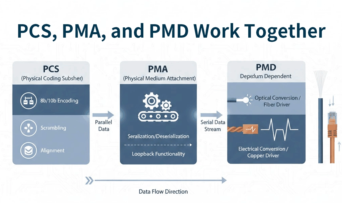
The flow of data through the PHY stack follows this pipeline:
Step 1: PCS Encodes and Organizes Data
Data from the MAC is:
Encoded (64b/66b or others)
Distributed into lanes (if multi-lane)
Aligned and block-locked
This prepares the data for high-speed serialization while maintaining signal integrity.
Step 2: PMA Converts and Synchronizes the Bitstream
PMA:
Serializes the PCS-coded data into a continuous bitstream
Recovers clock timing from incoming data
Applies SerDes equalization and retiming
Ensures lane bonding for multi-lane protocols (XLAUI, CAUI-4, etc.)
This stabilizes the signal before transmission.
Step 3: PMD Sends the Signal Through the Medium
The PMD layer:
Converts electrical signals into optical signals (via laser/photodiode)
Or adapts electrical outputs for copper (BASE-T, DAC)
On the receiving side, PMD reverses the process and passes clean electrical signals back to the PMA.
3. Why These Layers Matter
For optical transceiver performance
These layers determine:
Maximum data rate
Link distance capability
Error performance (BER)
Latency
Power efficiency
PMA and PMD are especially critical in 100G/200G/400G PAM4 transceivers, where clock recovery and optical modulation require advanced DSP.
For system integrators
A clear understanding of PCS-PMA-PMD interactions helps with:
Selecting compatible SFP/QSFP modules
Troubleshooting optical link issues
Ensuring correct lane mapping (e.g., breakouts)
Diagnosing coding or alignment errors
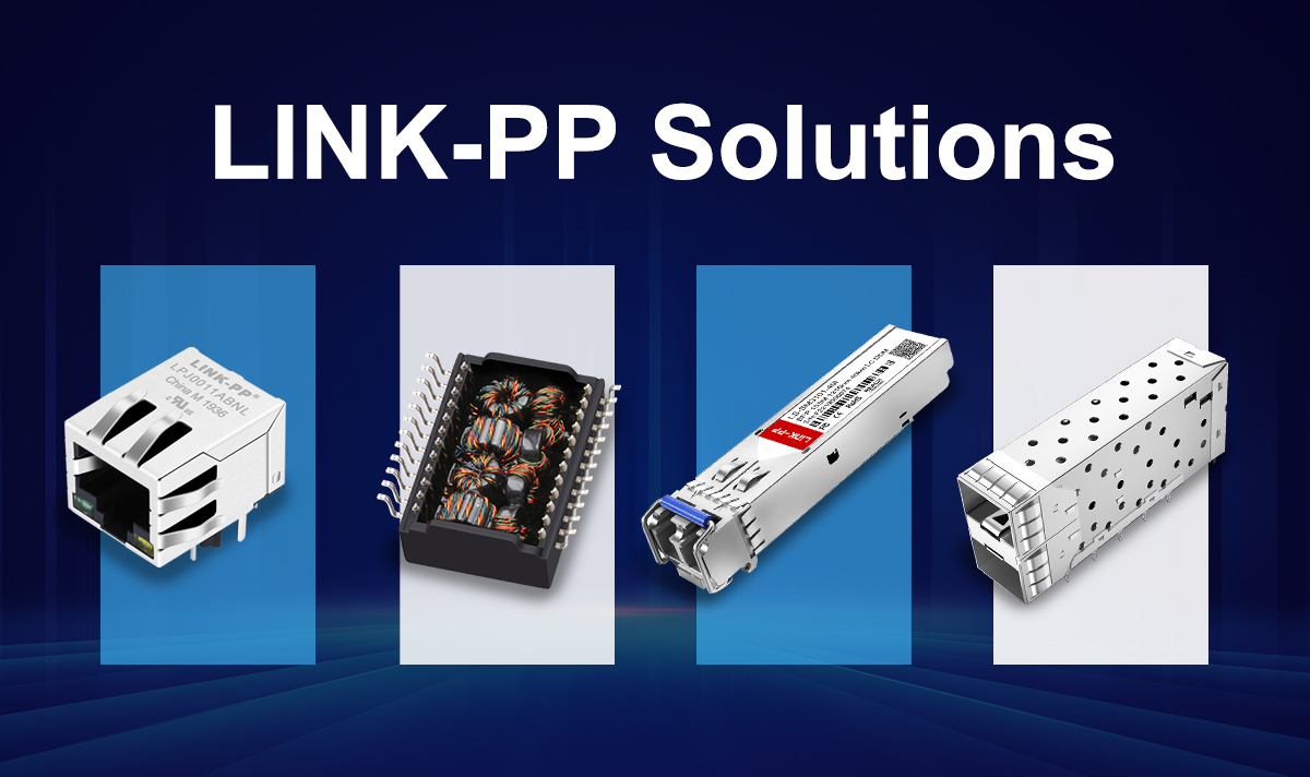
4. How LINK-PP Hardware Supports PCS/PMA/PMD Stability
LINK-PP provides Ethernet magnetic components, optical transceiver accessories, and high-performance connectivity parts engineered for:
Low insertion loss and high signal integrity (supports PMA SerDes performance)
EMI suppression for stable PCS/PMA operations
Robust electrical characteristics for long-distance links
Compatibility with major networking OEMs
High-quality connectors, RJ45 magnetics, and optical components help maintain signal clarity across all PHY sublayers, ensuring reliable operation from PCS encoding to PMD transmission.
Conclusion
PCS, PMA, and PMD work together as three synchronized layers of the Ethernet PHY, forming the essential pipeline that allows high-speed data to travel cleanly and reliably across fiber and copper networks.
PCS handles coding and alignment
PMA handles serialization and timing
PMD handles medium-specific transmission
Understanding their roles is fundamental when evaluating high-speed optical modules, network designs, or physical-layer performance.
FAQ
1. What is the difference between PCS, PMA, and PMD in Ethernet?
PCS (Physical Coding Sublayer) handles data encoding, block alignment, lane distribution, and error detection.
PMA (Physical Medium Attachment) performs serialization/deserialization (SerDes) and clock recovery.
PMD (Physical Medium Dependent) interfaces with the actual physical medium—launching and receiving electrical or optical signals.
2. Why do PCS, PMA, and PMD need to work together?
These three layers form the complete Ethernet PHY pipeline. PCS prepares data, PMA converts it into serialized bitstreams, and PMD transmits it over copper or fiber. Only by working together can the PHY maintain timing, signal integrity, and interoperability across high-speed links.
3. Does every Ethernet speed use PCS, PMA, and PMD?
Yes. Regardless of the speed—1G, 10G, 25G, 100G, or 400G—these blocks exist in the Ethernet PHY architecture. Their internal implementations may vary (e.g., different encoding schemes or SerDes lanes), but the functional structure remains consistent.
4. How does PCS affect link stability and performance?
PCS enhances link robustness by:
• performing block encoding (e.g., 64b/66b, 256b/257b)
• adding synchronization headers
• enabling lane distribution and deskew
• providing error detection (e.g., CRC/FEC)
These functions reduce bit error rates and support reliable long-distance, high-speed transmission.
5. What role does PMA play in optical transceivers?
In SFP, SFP+, SFP28, QSFP+, and QSFP28 modules, the PMA layer includes the SerDes and clock recovery circuits that match host-side electrical lanes with optical drivers. It ensures timing accuracy, data lane alignment, and seamless conversion between electrical and optical domains.
6. Is PMD only used for optical fiber?
No. PMD applies to both fiber and copper.
• In optical transceivers, PMD includes lasers, photodiodes, and modulation circuitry.
• In copper interfaces (e.g., BASE-T), PMD includes analog front ends, transformers, and RJ45 connections.
Its job is always to couple PHY signals into the physical medium.
7. How do these layers impact module compatibility?
For interoperability, PCS encoding, PMA SerDes behavior, and PMD optical/electrical specs must follow IEEE 802.3 standards. This ensures that transceivers—even from different brands—work seamlessly with switches, routers, and NICs as long as they share the same standard.


