


In the relentless pursuit of higher speeds and denser packaging, optical transceiver technology constantly evolves. Yet, amidst the rise of compact Small Form-Factor Pluggables (SFP, SFP+, QSFP+) and cutting-edge Coherent modules, the humble 1×9 optical transceiver remains a critical, reliable workhorse in numerous applications. Often overlooked in discussions dominated by the latest innovations, this robust form factor continues to deliver essential connectivity where simplicity, durability, and cost-effectiveness are paramount. Understanding where and why 1×9 modules persist offers valuable insight into the diverse landscape of optical networking.
☑ What Exactly is a 1×9 Optical Transceiver?
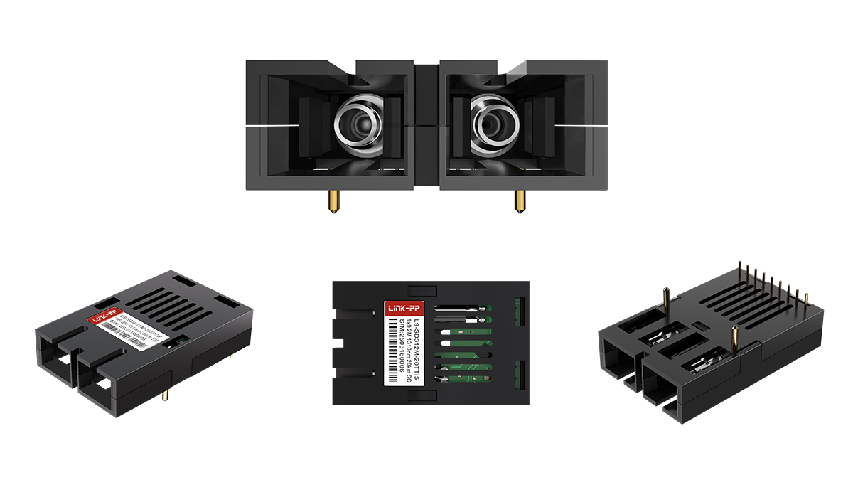
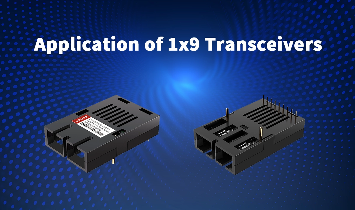
The name “1×9” refers to pin configuration: 1 row of 9 electrical pins for connecting to networking equipment. Unlike their pluggable successors, 1×9 transceivers are typically fixed devices. They are soldered directly onto the host printed circuit board (PCB) within networking equipment. This inherent design brings distinct advantages and limitations:
Key Advantages:
Robustness & Reliability: The fixed connection eliminates connector wear and tear, vibration issues, and potential points of failure associated with pluggable interfaces. This makes them exceptionally reliable.
Cost-Effectiveness: Simpler design and direct PCB mounting often result in a lower cost per unit compared to equivalent pluggable modules.
Space Efficiency (in Design): For equipment manufacturers, integrating fixed 1×9 optical modules can sometimes allow for more compact overall device designs, as they don’t require cages, latching mechanisms, or front-panel access.
Power Efficiency: Generally, they consume slightly less power than pluggable equivalents due to the lack of complex control circuitry for hot-plugging.
Deterministic Performance: Fixed configuration simplifies design and testing for OEMs.
Key Limitations:
Non-Pluggable: Cannot be easily replaced or upgraded without soldering, requiring technician intervention and potentially taking the entire system offline.
Limited Configuration Flexibility: Port types and speeds are fixed at the time of equipment manufacturing.
Lower Speeds: Primarily used for legacy and industrial speeds like Fast Ethernet (100Mbps), Gigabit Ethernet (1Gbps), 1G/2G Fibre Channel, and lower-rate SONET/SDH (OC-3/STM-1, OC-12/STM-4, OC-48/STM-16).
☑ Where 1×9 Optical Transceivers Shine: Core Applications
Despite the dominance of pluggables in data centers and enterprise core networks, 1×9 transceiver applications remain vital in specific sectors:
Industrial Networking & Automation:
Harsh Environments: Manufacturing plants, power utilities, oil & gas facilities, and transportation systems demand extreme reliability. The ruggedness of fixed 1×9 optical modules makes them ideal for resisting temperature extremes, dust, moisture, and vibration. Think industrial SFP alternative.
Machine-to-Machine (M2M) Communication: Connecting PLCs, sensors, HMIs, and control systems often requires robust, simple Gigabit or Fast Ethernet links over fiber. 1×9 SFP equivalent modules provide this reliably.
Protocol Support: Widely used with industrial protocols like PROFINET, EtherNet/IP, and Modbus TCP/IP running over fiber for electrical noise immunity and longer distances.
Telecommunications Access & Legacy Infrastructure:
Customer Premises Equipment (CPE): Older Optical Network Terminals (ONTs), Digital Subscriber Line Access Multiplexers (DSLAMs), and Multiplexers (MUXs) frequently utilize fixed 1×9 optical modules for uplink connections (e.g., Gigabit Ethernet or lower-speed SONET/SDH) due to their proven reliability and cost structure.
Legacy SONET/SDH Equipment: Much existing metro and access layer telecom infrastructure, especially in remote areas or for specific services, still relies on OC-3/12/48 rates delivered via 1×9 optical transceivers. Maintaining this infrastructure requires compatible modules.
Low-Cost Fiber Aggregation: For aggregating lower-speed links in access networks or remote cabinets, 1×9 solutions remain a cost-effective choice.
Embedded Systems & Specialized Equipment:
Medical Devices: Imaging systems, diagnostic equipment, and hospital network infrastructure sometimes leverage the reliability of fixed fiber optic modules.
Military & Aerospace: Ruggedized communication systems benefit from the durability and fixed nature of 1×9 form factor optics.
Test & Measurement Equipment: Certain specialized instruments incorporate fixed optics for internal communication or specific interface requirements.
Broadcast & Professional AV: Where robust, jitter-free signal transmission over fiber is needed in fixed installations.
Cost-Sensitive Network Deployments:
Emerging Markets & SMBs: For basic fiber connectivity needs (e.g., connecting two buildings with Gigabit Ethernet) where the absolute lowest cost and maximum reliability are key, equipment using fixed 1×9 optical modules can be an attractive solution.
☑ Comparing 1×9 to Pluggable Form Factors
Understanding the positioning of 1×9 optical transceivers requires comparison:
Feature | 1×9 Optical Transceiver | SFP/SFP+ Module | Key Differentiator |
|---|---|---|---|
Form Factor | Fixed (Soldered) | Pluggable (Hot-swappable) | Serviceability & Upgradability |
Installation | Soldered to PCB (OEM Level) | User-Installable | Ease of Replacement |
Primary Speeds | FE, 1GbE, 1G/2G FC, OC-3/12/48 | 1GbE, 10GbE, 16G FC, Higher | Speed Capability |
Cost (Module) | Generally Lower | Generally Higher | Bill of Materials |
Robustness | High (Fixed Connection) | Medium (Depends on Connector) | Reliability in Harsh Environments |
Flexibility | Low (Fixed at Build) | High (Field Configurable) | Network Adaptability |
Power Consumption | Generally Lower | Generally Higher | Energy Efficiency |
Typical Use Case | Industrial, Legacy Telecom, Embedded Systems | Data Centers, Enterprise Networks, Modern Telecom | Application Suitability |
☑ LINK-PP: Your Trusted Partner for 1×9 Optical Solutions

As a leader in optical transceiver solutions, LINK-PP understands the critical role reliable legacy components play. We offer a comprehensive range of high-quality, MSA-compliant 1×9 optical transceivers designed for maximum performance and longevity in demanding applications. Whether you’re an OEM integrating optics into industrial switches or a service provider maintaining legacy telecom infrastructure, LINK-PP provides the dependable connectivity you need.
Common LINK-PP 1×9 Optical Transceiver Models Include:
LINK-PP L9-SD311G-10CTC: 1000BASE-LX, Single mode, 1310nm, 10km, Dual SC, CML Differential Input/Output and TTL signal detect
LINK-PP L9-SD311G-20PPC: 1000BASE-LX, 1310nm, Single-mode, 20km, Dual SC, PECL Differential Input/Output and PECL signal detect
LINK-PP L9-SD311G-20PTC: 1000BASE-LX, 1310nm, Single-mode, 20km, Dual SC, PECL Differential Input/Output and TTL signal detect
☑ Ensuring Compatibility and Performance
When sourcing 1×9 optical transceivers, especially from third-party manufacturers like LINK-PP, compatibility is crucial. Reputable suppliers ensure:
MSA Compliance: Adherence to Multi-Source Agreement mechanical and electrical specifications.
Rigorous Testing: Full testing against industry standards (IEEE, Telcordia, etc.) and often vendor-specific parameters.
Quality Components: Use of high-grade lasers, detectors, and PCBs for reliability.
Long-Term Availability: Commitment to supporting legacy technologies.
☑ Troubleshooting Tips for 1×9 Modules
Since they are fixed, issues often point to the module itself or the host board:
No Link Light: Check fiber continuity (clean connectors!), verify wavelength and fiber type match (MM/SM), confirm correct speed/duplex settings on the host port. Rule out host board failure.
Intermittent Link/Errors: Suspect dirty fiber connectors, marginal optical power levels (check specs), potential damage to the fiber cable, or host board issues. Vibration can sometimes affect solder joints (rare).
Complete Failure: Often indicates a failed 1×9 optical transceiver or a failure on the host board. Requires technical diagnosis and potentially board-level repair/replacement.
☑ Conclusion: The Unseen Backbone
While not grabbing headlines like 800G coherent modules, the 1×9 optical transceiver remains a foundational technology. Its unique blend of robustness, reliability, and cost-effectiveness ensures its continued relevance in industrial automation, legacy telecommunications, embedded systems, and cost-sensitive deployments. For applications demanding unwavering performance in challenging environments without the need for field upgrades, the 1×9 form factor is often the optimal optical transceiver solution.
See Also
What You Need to Know About 1×9 Optical Transceivers
Join The Vibrant And Growing LINK-PP Community Today
Understanding the Differences of SFP, SFP+, SFP28, QSFP+, and QSFP28 Optical Transceivers


